A logic gate is an elementary building block of a digital circuit. Most logic gates have two inputs and one output. At any given moment, every terminal is in one of the two binary conditions OFF (0) or ON (1).
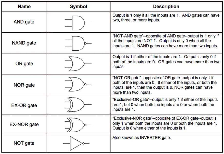
During our TEJ20 classes, we learned about the logic gates and truth tables. The logic gate has a symbol showing which gates are used and how the inputs go in, and what outputs come out. Each logic gate has a boolean expression summing up the final output of the whole logic gate system. Accompanying the symbol is the truth table, which shows the different steps in the logic gate, and in terms of 0's and 1's proves if the gate is in the ON or OFF state.
During our TEJ20 classes, we learned about the logic gates and truth tables. The logic gate has a symbol showing which gates are used and how the inputs go in, and what outputs come out. Each logic gate has a boolean expression summing up the final output of the whole logic gate system. Accompanying the symbol is the truth table, which shows the different steps in the logic gate, and in terms of 0's and 1's proves if the gate is in the ON or OFF state.
Types of Logic Gates, symbols and description we learned about in class.
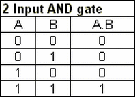
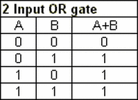
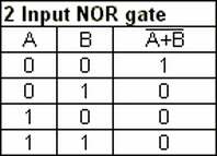
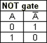
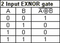
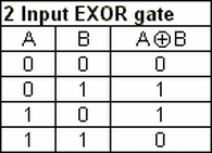
Here are the Truth Tables for the Logic Gate diagrams:
|

|
|
|
|
|
|
